
Giving you more fuel tank options
One of the great things about catamarans is the redundancy in just about every system. Fuel tanks are no exception and having a tank for each engine is nice, but it can be made nicer with a transfer pump or better yet, the ability to pick the tank that each engine pulls its diesel from.
But why?
There are couple of reasons that you may want to do this.
Maybe one engine is not working and you want to be able to go further by using fuel from both tanks for the engine that is working.
If you are getting fuel from an area where this is concern about the quality, you can fill one tank with the suspect fuel, and if it in fact turns out to be bad, you still have the other tank that is known good to fall back on.
We normally run both engines from one tank just so that it is a little bit easier to fill when the time comes. This is a minor issue on our Vision 444, since the two fuel tanks are just in front of the base of the mast. The filler hose doesn't have to move far to fill one versus the other, but it's still nice to only have to open one tank filler! By doing this, if we want to run from diesel injector cleaner through the system, we only have to add it to one tank to do so.
I'm convinced, what's it take?
The gotcha
One thing that must be understood first, is that in a diesel engine, diesel fuel flows in a loop, unlike a gasoline engine. The low pressure pump may deliver 4 liters per hour to the engine, but only a portion of that is used in combustion and the rest must be returned to the tank from which it came.
What exactly happens? (skip if you don't care)
A low pressure, higher volume pump brings fuel into the engine's fuel circuit. This pump can be either electric, or mechanical (operated by lever on the pump being operated by a fuel cam within the engine). Then a high pressure, low volume pump increases the pressure to be enough to be injected into an already pressurized cylinder or into a pre-cylinder area (indirect injection). Either way, the pressure from this pump can be on the order of 2500psi in an indirect injection engine (like our Nanni engine) or can be as high as 30,000psi in a common rail engine (like the newest Yanmars). Because of these huge pressures, if too much fuel is delivered, something is going to break. Diesel injectors have a valve, almost like a blow-off valve in a turbocharger; pressure above a set point escapes and leads to a tube that returns to the fuel tank. The added benefit is that creating all this pressure increases heat; some extra heat is dissipated as the fuel returns to the tank in the return line.

A special valve
So in order to make a fuel selector valve for a diesel engine to work, it must switch two sets of ports when the valve is manipulated. It's equivalent to a double pole, double throw electrical switch.
Both valves are mounted to the top of our fuel tanks and there is basically a port engine valve and a starboard engine valve. Changing the valves changes from which tank that engine pulls (and deposits) its fuel.
Here is what the configuration looks like in diagram form:

The Parts
In addition to the valves, there are also some fittings that are required. You may need to adjust the hose barb sizes to fit the fuel lines in your boat, but don't try to get combo right angle barb fittings!!! Mainly because you won't be able to thread them into the valve. The valves, elbows and barbs have to be assembled in a particular order in order to make it possible.
The following parts assume that the fuel lines are 8mm / 5/16" inside diameter. If yours are not, adjust those fittings accordingly.
 |
| Groco 6-Port NPT Bronze Fuel Valve 1/2 Main - 3/8 Return (Order 2) |
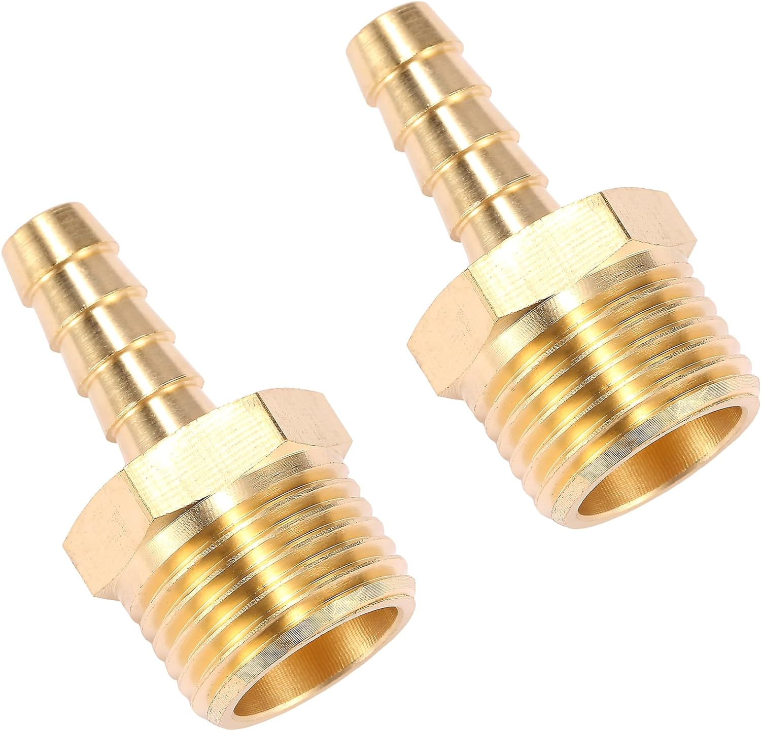 |
| 2 Pack Brass Hose Fitting, Adapter,5/16" Barb x 1/2" NPT Male Pipe (Order 3) |
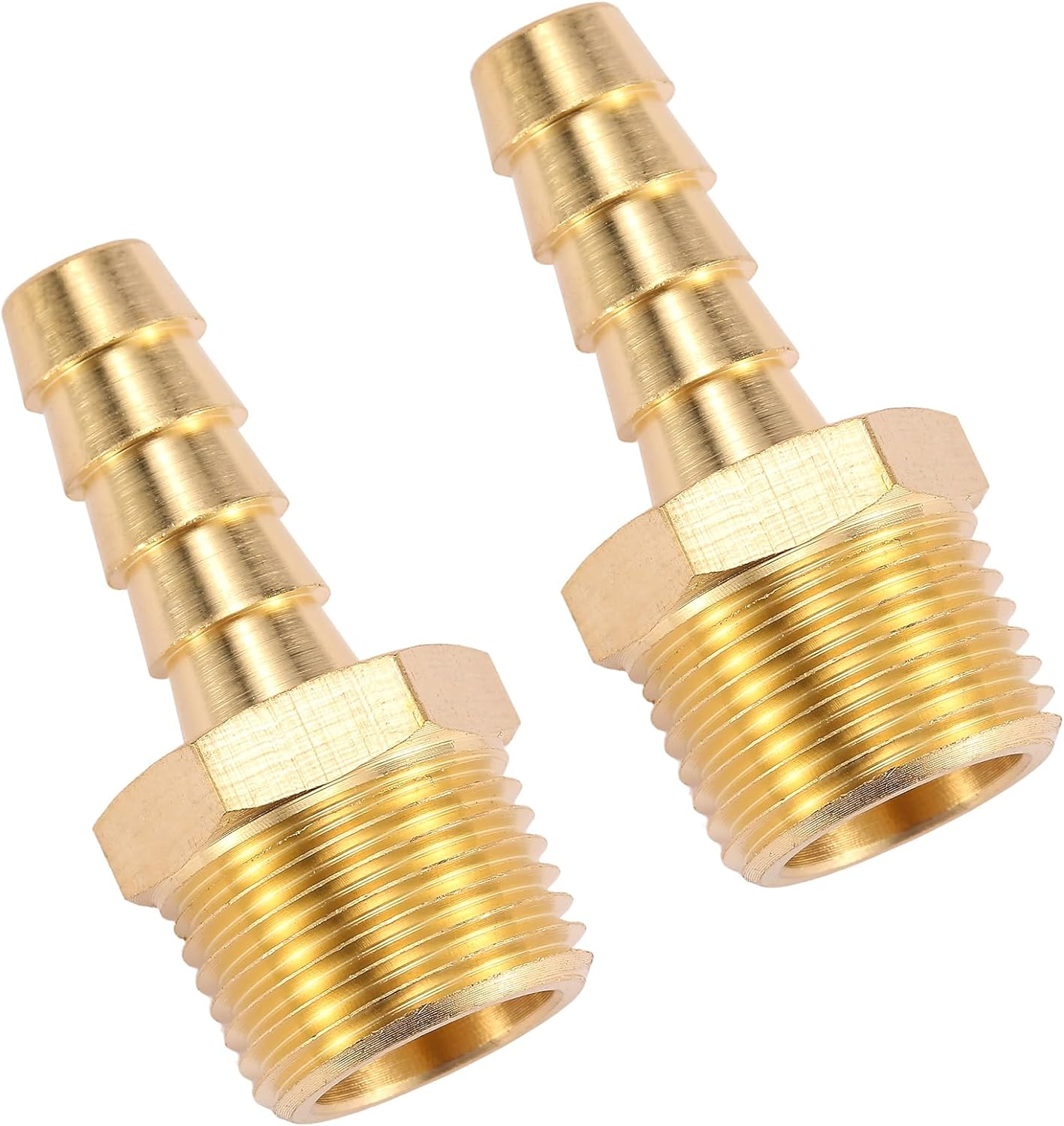 |
| 2 Pack Brass Hose Fitting, Adapter, 5/16" Barb x 3/8" NPT Male Pipe (Order 2) |
 |
| Joywayus Brass Hose Fitting,90 Degree Elbow,5/16" Barb x 3/8" NPT Male Pipe Water/Fuel/Air(Pack of 2) |
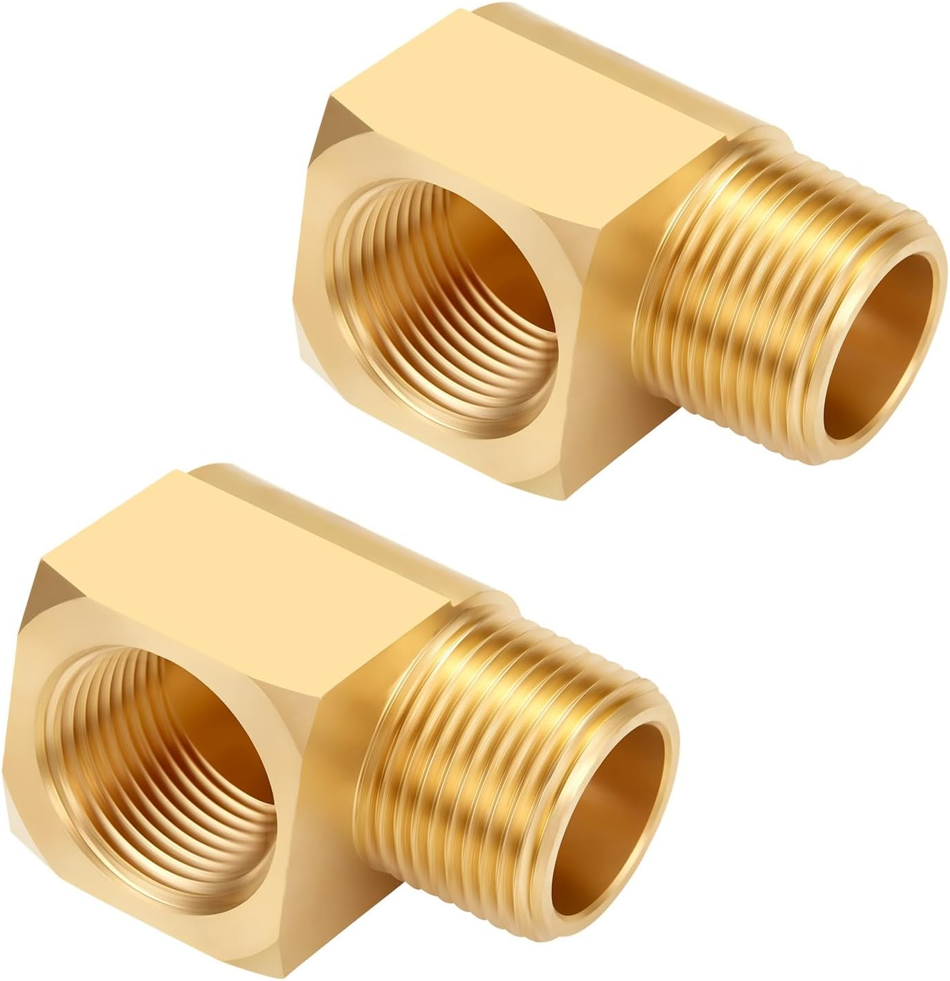 |
| Litorange 2 PCS Metals Brass Pipe Fitting 90 Degree Barstock Street Elbow 1/2" NPT Male Pipe x 1/2" NPT Female Pipe |
 |
| Gasoila - SS04 Soft-Set Pipe Thread Sealant with PTFE Paste, Non Hardening, -100 to 600 Degree F, 1/4 Pint Brush |
If your fuel tank pickups only have one supply and one return fitting, you will also need the following Y connectors.
 |
| Quickun 5/16" ID Hose Brab, Brass Shaped Y 3 Ways Barbed Hose Fitting Intersection Split Splicer Joint Union Adapter for Water/Fuel/Air (Pack of 4) |
 |
| MarineNow Premium Marine Grade 316 Stainless Steel Hose Clamps 12.7 mm Band, Choose Size and Pack Quantity [SAE:8 (11-23mm,7/16"-15/16"), 25-Pack] |
 |
| Continental 65127 5/16" ID Fuel Hose - 50 psi - SAE 30R7 - 25' Length |
 |
| 1/2-Inch Plastic Pipe Clamp, 2-Hole Mount Strap for 5/8" OD Pipe (10-Pack)- Color may vary |
Assembly Order
Because of the closeness of the fittings, you will have to assemble the valves in a specific order.- Figure out where you are going to mount the valves so you know which way 90 degree fittings should be oriented to make installation easier.
- Insert the 90 degree 3/8" barb into Port 4 (the smaller, top threaded opening). Tighten until the barb is pointing either towards port 5 or port 6 (whichever works better for your installation)
- Insert the 1/2" street elbow into Port 3 (the larger, top threaded opening). Tighten until the opening is pointing in the orientation that works for your installation. (Do not point it towards the lever.)
- You will now have 5 openings remaining (two 3/8" and three 1/2"). Fill these will the appropriate barbs and fully tighten.
- Repeat steps 1-4 for your other valve.
Installation
The pickup will be the tube that goes to the bottom of the tank.
If you only have one fuel supply pickup per tank, it will first have to go to the same-side pickup "Y".)
The pickup will be the tube that goes to the bottom of the tank.
If you only have one fuel supply pickup per tank, it will first have to go to a opposite-side pickup "Y".)
Note:
If you only have one fuel return per tank, it will first have to go to a same-side return "Y".)
Note:
If you only have one fuel return per tank, it will first have to go to a opposite-side return "Y".)
Labeling, labeling, labeling.
Label the valves so you will quickly know how to set them for the desired operation.
When the handle is facing towards port 1, the fuel is shut off.
When the handle is facing towards port 3 (pointing out), fuel is being pulled from the "same-side" tank.
When the handle is facing towards port 2, fuel is being pulled from the "opposite-side" tank.
 |
| Instructions for use |
 |
| Starboard side valve in Mia |
Bleed the system
- Set both valves to supply fuel from the "same-side" as the engine, ie., port from port, starboard from starboard.
- If your fuel tanks are below your engines, you may have an electric pump that needs to be powered.
- Open the bleed screw for the port engine
- Place a container under your fuel filter to catch the excess fuel; it may be a lot depending on how far the tanks are from your engines.
- Repeatedly press the Fuel primer level until fuel begins to flow from the bleed screw. Normally, once flowing, it will continue. Let this continue until you see bubbles pass through and then it runs clear without bubbles.
- Close the bleed screw.
- Repeat steps 2-6 for the starboard engine.
- Switch the fuel valves to supply fuel from the "Opposite-side" as the engine, ie., port from starboard, starboard from port.
- Repeat steps 2-6 for the port engine.
- Repeat steps 2-6 for the starboard engine.
- Turn off any electric pump that may have been turned on.
- The system is now blead.
Test the system
- Disconnect the return hose that goes from each valve and have it go into a small container.
Run one engine at a time, and make sure that fuel would be returning to the tank you expect.
Reconnect the hoses. - To make sure that fuel is being pulled from where you expect, start with tanks that are adequately full, and make a note of the starting fuel gauge level. Run both engines from one side. Make sure that only the expected tank level decreases.
- During the first couple of engine uses after installing, make sure that neither tank increases in fuel level.
Comments
Post a Comment